RigSpline Node
A C++ Maya Plugin I developed to increase performance in character rigs.

Building matrices from splines/surfaces are often a performance bottleneck in character rigs. The "rigSpline" node was built to speed up performance by doing spline/surface calculations inside a c++ node.
Practical Usage
Connect Joints
First, lets create a
rigSplinenode and connect thetranslate, rotate, scaleinto a set of joints. We will also parent the joints under :root/joint_parentand create a cube under each joint to make it easier to see in the viewport
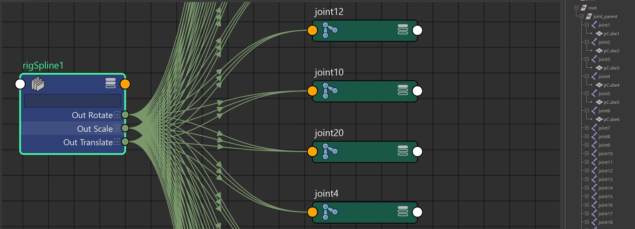
import maya.cmds as mc
root = mc.createNode('transform', name='root')
spline_node = mc.createNode('rigSpline')
JOINT_COUNT = 25
joint_parent = mc.createNode('transform', name='joint_parent', parent=root)
spline_joints = []
for i in range(JOINT_COUNT):
    spline_joint = mc.createNode('joint', parent=joint_parent)
    cube_transform, cube_node = mc.polyCube()
    mc.setAttr('%s.width' % cube_node, 1)
    mc.setAttr('%s.height' % cube_node, 0.25)
    mc.setAttr('%s.depth' % cube_node, 1)
    mc.parent(cube_transform, spline_joint)
    mc.connectAttr('%s.outTranslate[%s]' % (spline_node, i), '%s.translate' % spline_joint)
    mc.connectAttr('%s.outRotate[%s]' % (spline_node, i), '%s.rotate' % spline_joint)
    mc.connectAttr('%s.outScale[%s]' % (spline_node, i), '%s.scale' % spline_joint)
    spline_joints.append(spline_joint)
Connect Controls
Next, we can connect a series of locators to the
inMatricesattribute We will also parent the controls under a transform:root/control_parent
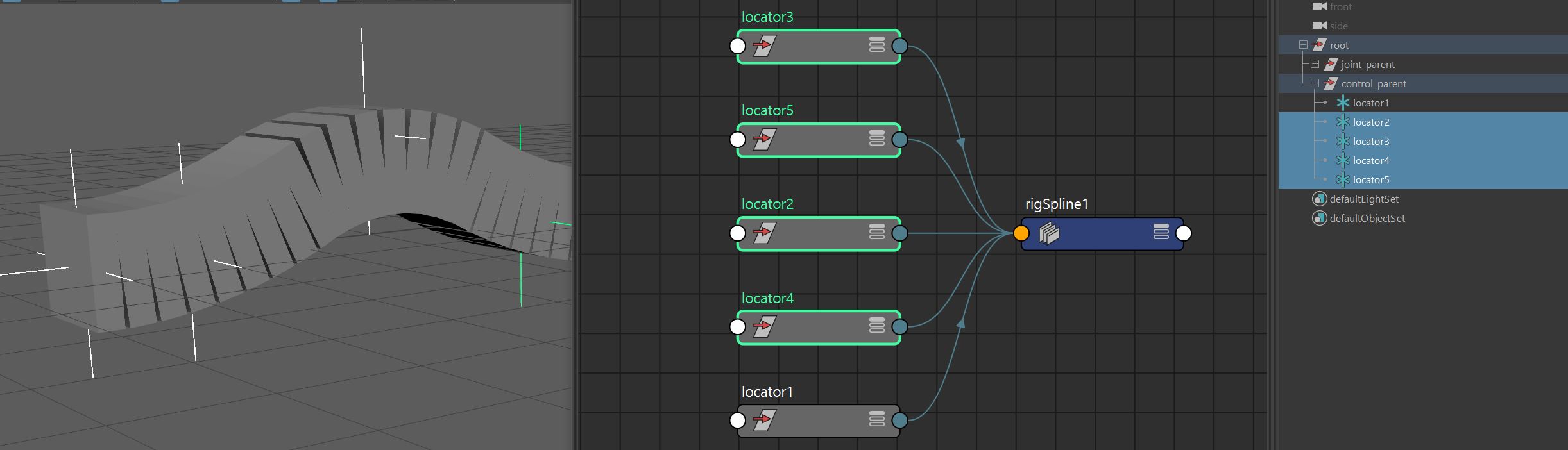
control_parent = mc.createNode('transform', name='control_parent', parent=root)
positions = [
    [0.0, 0.0, 1.0],
    [0.0, 0.0, 2.0],
    [0.0, 1.0, 4.0],
    [0.0, 0.0, 6.0],
    [0.0, 0.0, 7.0]
]
controls = []
for i in range(len(positions)):
    control = mc.spaceLocator()[0]
    mc.setAttr('%s.rx' % control, 90.0)
    mc.setAttr(
        '%s.translate' % control,
        positions[i][0],
        positions[i][1],
        positions[i][2],
        type='double3'
        )
    mc.connectAttr('%s.worldMatrix[0]' % control, '%s.inMatrices[%s]' % (spline_node, i))
    controls.append(control)
    mc.parent(control, control_parent)
Grow Attribute
The grow attribute multiplies each joints position down the length of the curve.
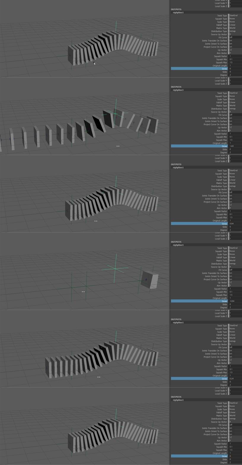
Slide Attribute
The slide attribute adds to each joints position down the length of the curve.
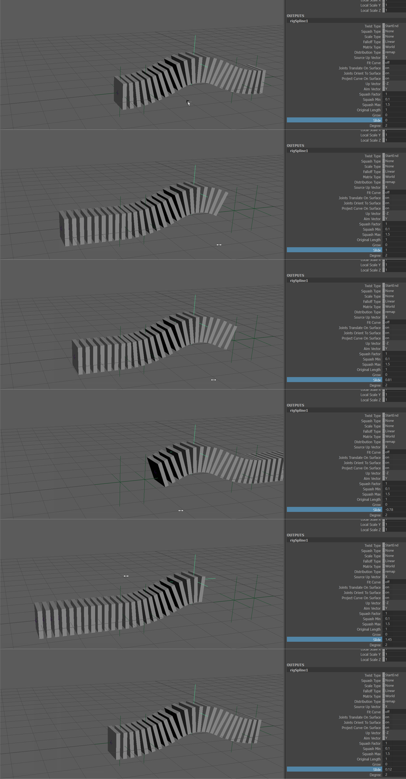
Fit Curve
The fitCurve attribute forces the curve to intersect the control points.
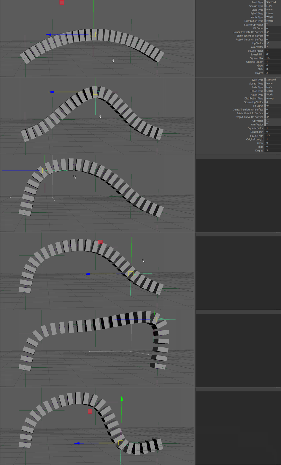
NOTE Fit curve works best with degree above 2
Degree
if you need to change the degree of the curve, you can use splineNode.degree attribute
DEGREE = 2
mc.setAttr('%s.degree' % spline_node, DEGREE)
Project On Surface
rigSplines can be projected on a surface using the inSurface attribute.
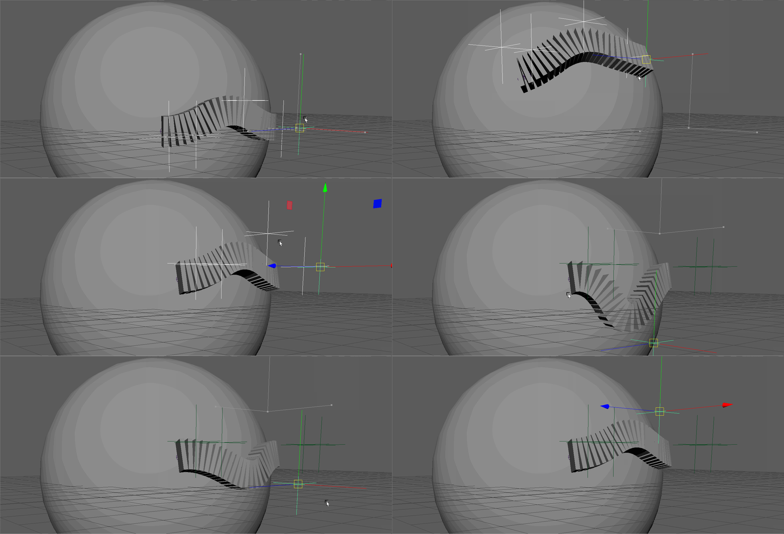
Connect <NURBS_SURFACE>.worldSpace[0] to rigSpline.inSurface
sphere_transform, sphere = cmds.sphere( r=5 )
sphere_shape = mc.listRelatives(sphere_transform, c=True, type='nurbsSurface')[0]
mc.select(mc.ls('%s.cv[*]' % sphere_shape))
mc.move(-6, 0, 3 , r=True)
mc.connectAttr('%s.worldSpace[0]' % sphere_shape, '%s.inSurface' % spline_node)
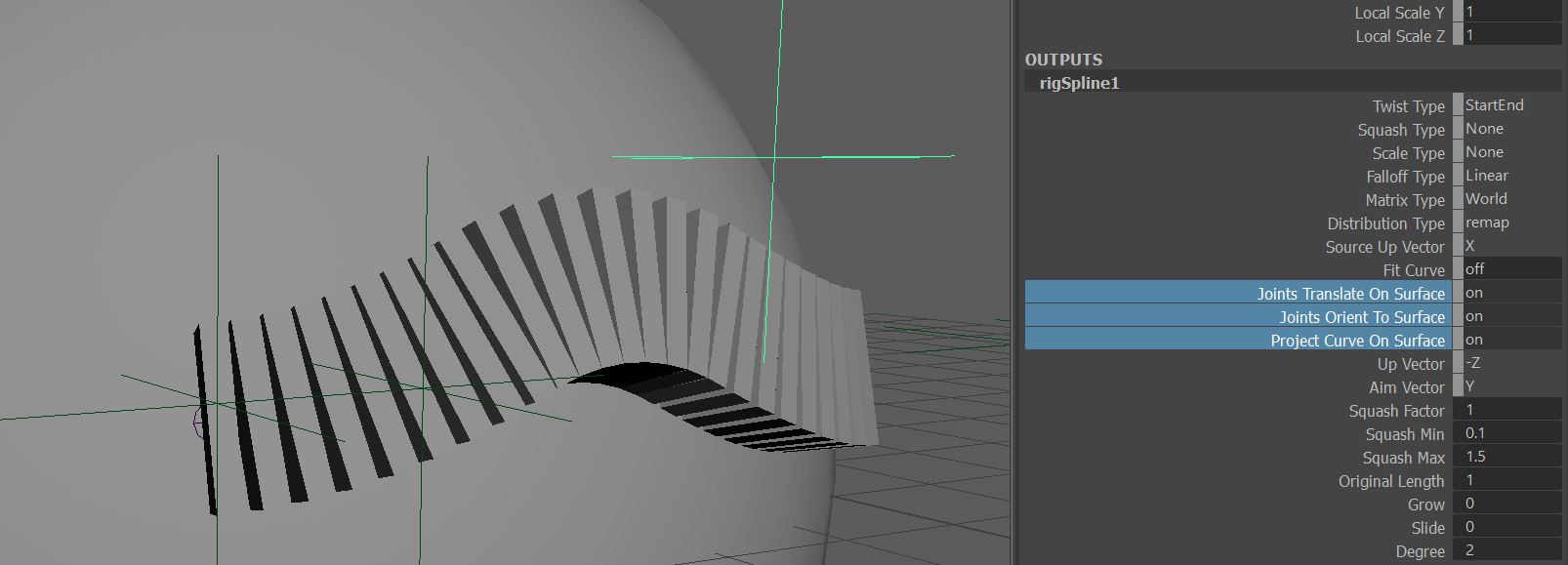
**Note The exact way in which the joints get projected onto the surface can be tweaked with JointsTranslateOnSurface, JointsOrientToSurface and ProjectCurveOnSurface attributes
ParentMatrix
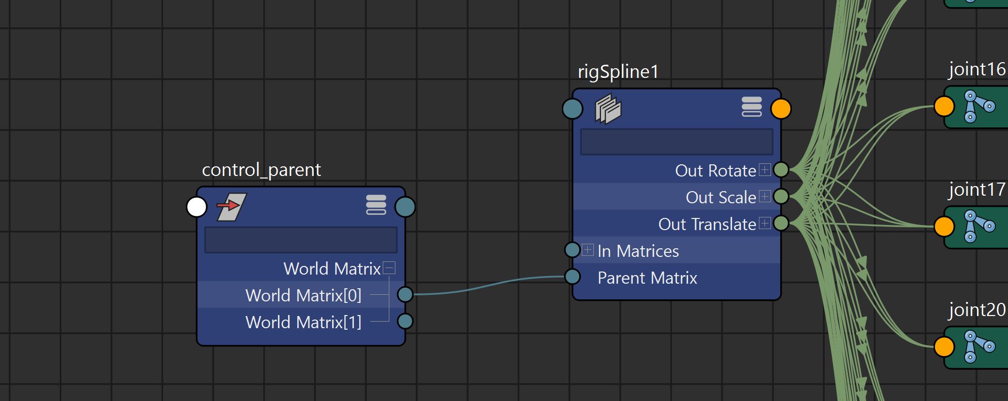
The parent matrix represents the space in which the calculations are done.
From Root
In most cases we simply connect the parent of both the joints and the controls (root).
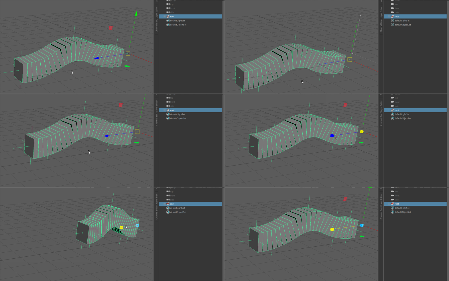
Connect root.worldMatrix[0] to rigSpline.parentMatrix
mc.connectAttr('%s.worldMatrix[0]' % root, '%s.parentMatrix' % spline_node)
From Control Parent
In some cases it is useful to connect only the parent of the controls so that we can calculate joints in another space.
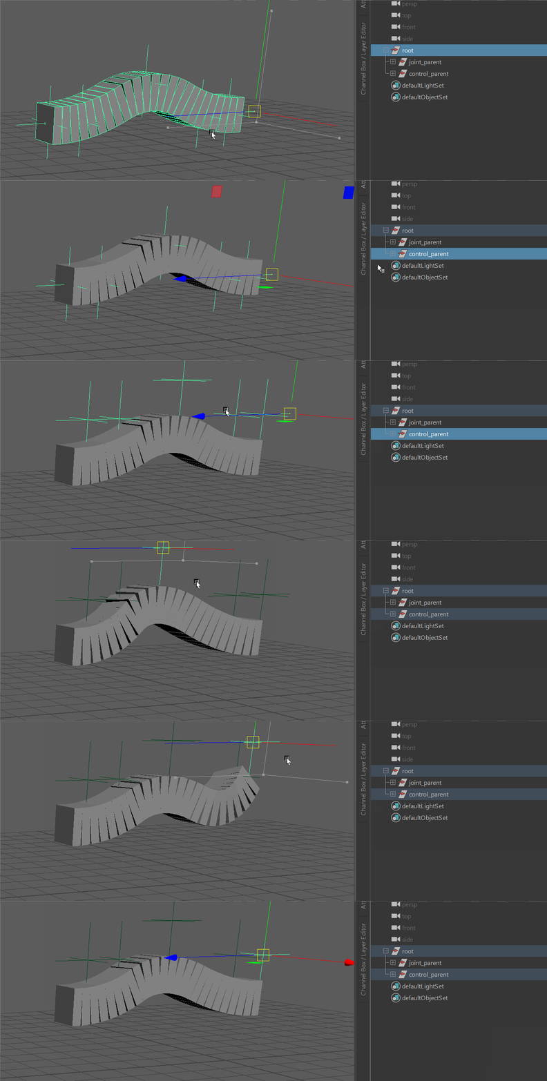
Connect control_parent.worldMatrix[0] to rigSpline.parentMatrix
mc.connectAttr('%s.worldMatrix[0]' % control_parent, '%s.parentMatrix' % spline_node)
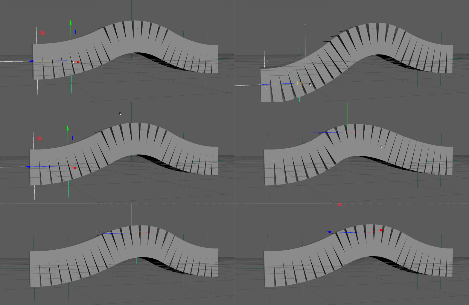
Remap Distribution
By default the distribution mode is set to remap
Notice how this distributes the joints evenly down the length of the curve creating a sliding effect.
Parameter Distribution
Sometimes we need to pick the exact position for each joint in parameter space.
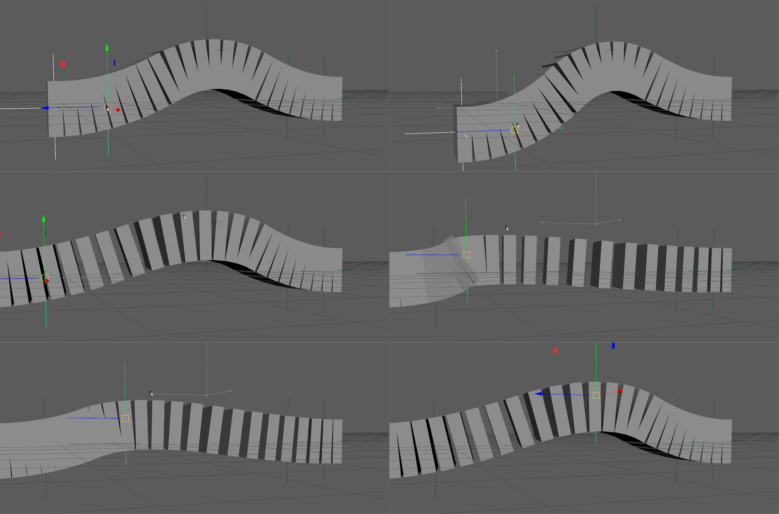
Set the
distributionTypeattribute to2(parameter distribution) Then lets set asplineNode.inParametersvalue for each of the joints
mc.setAttr('%s.distributionType' % spline_node, 2)
for i in range(len(spline_joints)):
    mc.setAttr('%s.inParameters[%s]' % (spline_node, i), 1.0/(len(spline_joints)-1) * i)
Notice how each joint is stuck to that exact curve parameter creating a stretching effect.
Lock Length Distribution
Often, in the case of spines, necks or tails, we need to lock the length or the joint chain no matter the length of the curve itself.
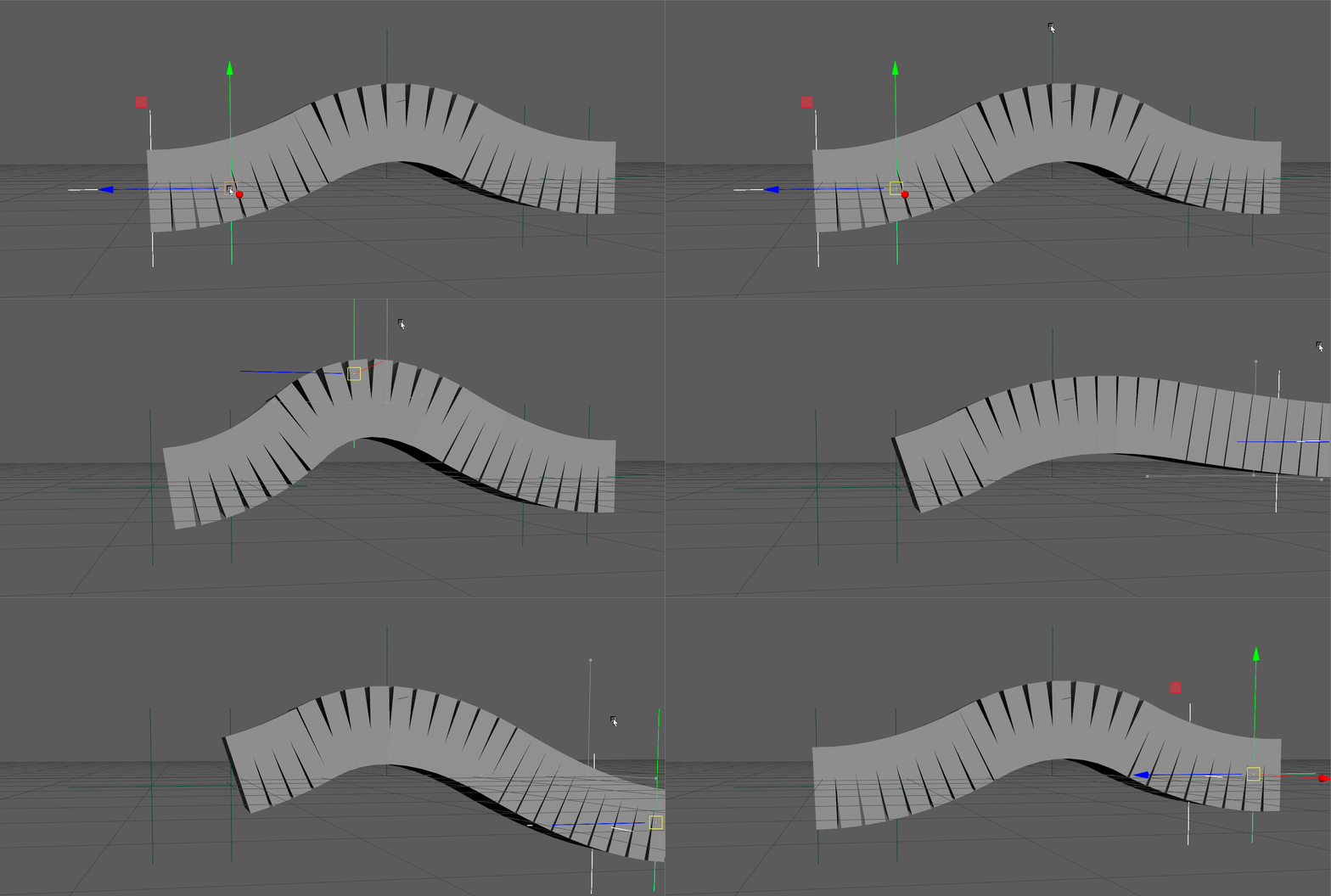
Set the
distributionTypeattribute to1(lockLength distribution) Then We need to set theoriginalLengthattribute to let the node know what the starting length was.
import maya_tools.utilities.nurbs_curve_utilities as ncu
mc.setAttr('%s.originalLength' % spline_node, ncu.get_predicted_curve_length(positions, DEGREE, 0))
mc.setAttr('%s.distributionType' % spline_node, 1)
**Note Since the nurbs curve is internal to the node, we can't measure it in traditional ways. Instead, we can use
get_predicted_curve_length()to figure out the predicted curve length with just the control positions and degree.
Start/End Squash
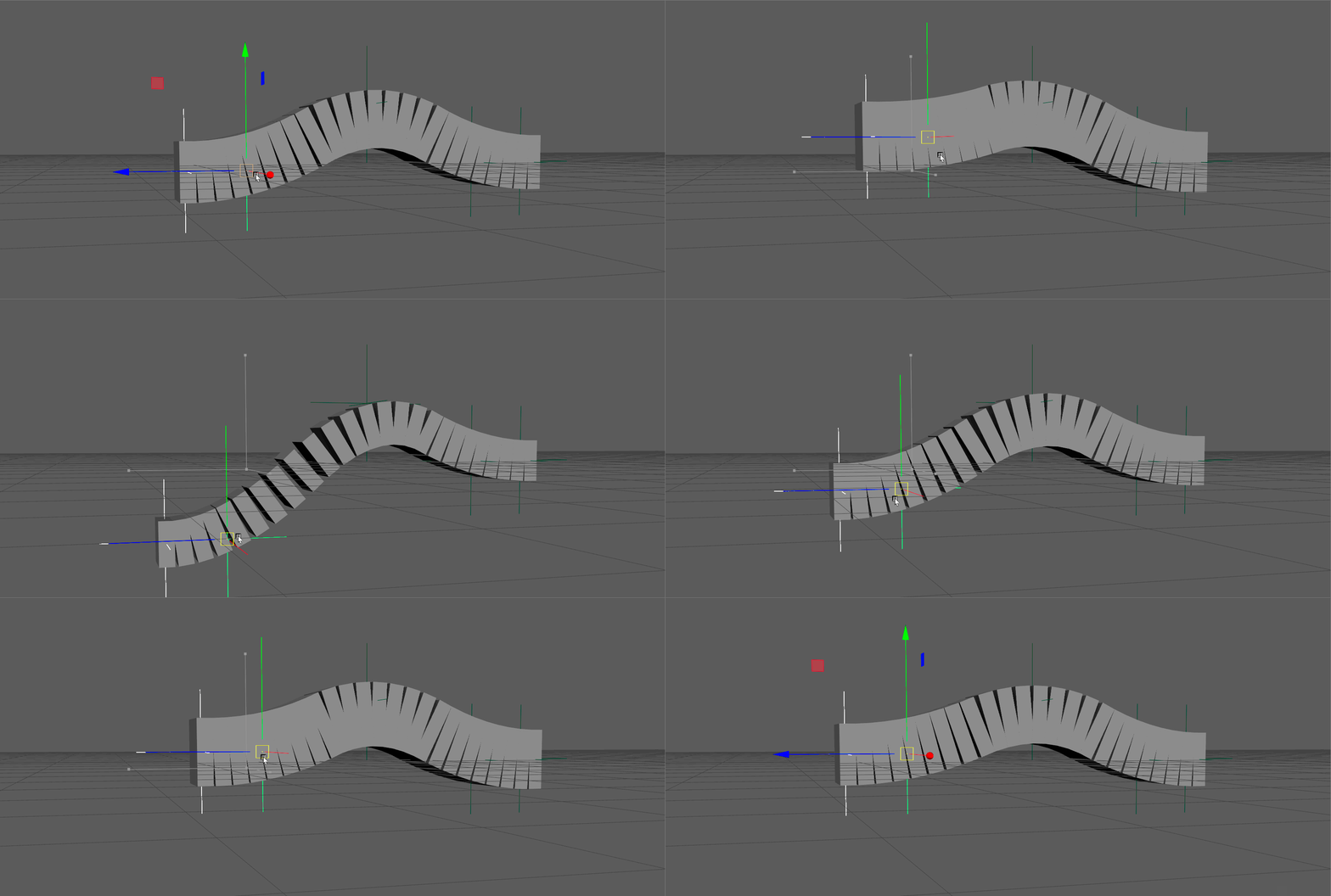
Control joint width based on how much the entire curve length has changed.
Set the squashType attribute o 1 (StartEnd).
mc.setAttr('%s.squashType' % spline_node, 1)
mc.setAttr('%s.distributionType' % spline_node, 2)
**Note: To actually see the results of squashing, you should set the distribution mode to parameter or remap.
Segment Squash
Control joint width based on how much the distance between joints has changed.
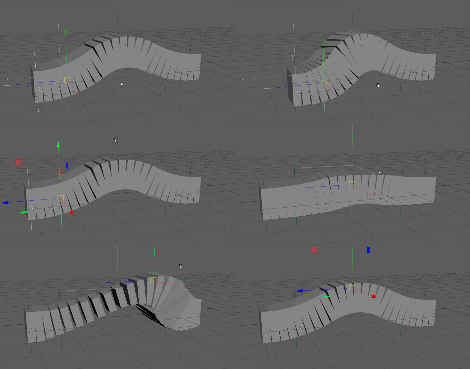
Set the
squashTypeattribute to 2 (Segment) Measure the distance between each joint and set thesegmentLengthsattribute accordingly. This allows the node to know how long each joint is in its resting state.
mc.setAttr('%s.squashType' % spline_node, 2)
mc.setAttr('%s.distributionType' % spline_node, 2)
for i in range(len(spline_joints)):
    this_position = mc.xform(spline_joints[i], q=True, ws=True, t=True)
    if i == len(spline_joints)-1:
        other_position = mc.xform(spline_joints[i-1], q=True, ws=True, t=True)
    else:
        other_position = mc.xform(spline_joints[i+1], q=True, ws=True, t=True)

    local_positon = [this_position[x] - other_position[x] for x in range(3)]
    segment_length = sqrt(sum(x**2 for x in local_positon))
    mc.setAttr('%s.segmentLengths[%s]' % (spline_node, i), segment_length)
Squash Settings
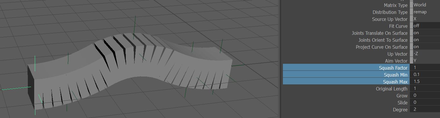
Squash factor and upper/lower limits can be set here:
Start/End Scale
Control joint width using start and end points.
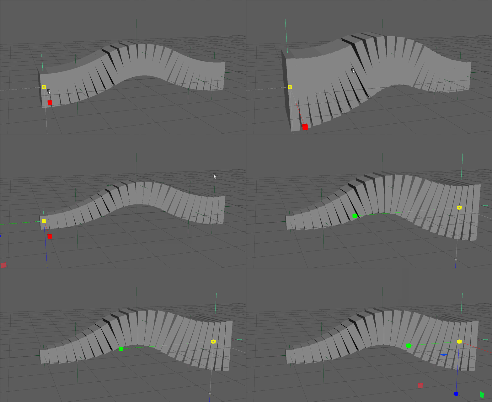
Set the
scaleTypeattribute to 1 (StartEnd).
mc.setAttr('%s.scaleType' % spline_node, 1)
Segment Scale
Control joint width using distance between joints.
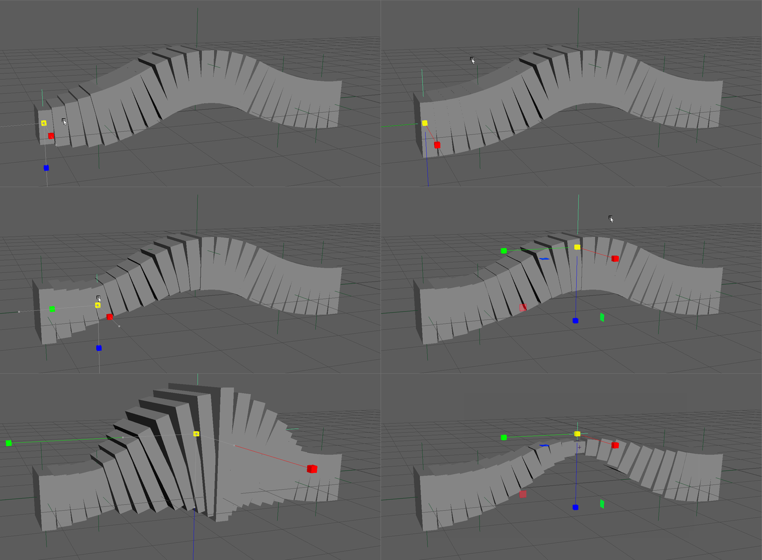
Set the scaleType attribute to 2 (Segment).
mc.setAttr('%s.scaleType' % spline_node, 2)
Start/End Twist
Control joint twist using start and end points.
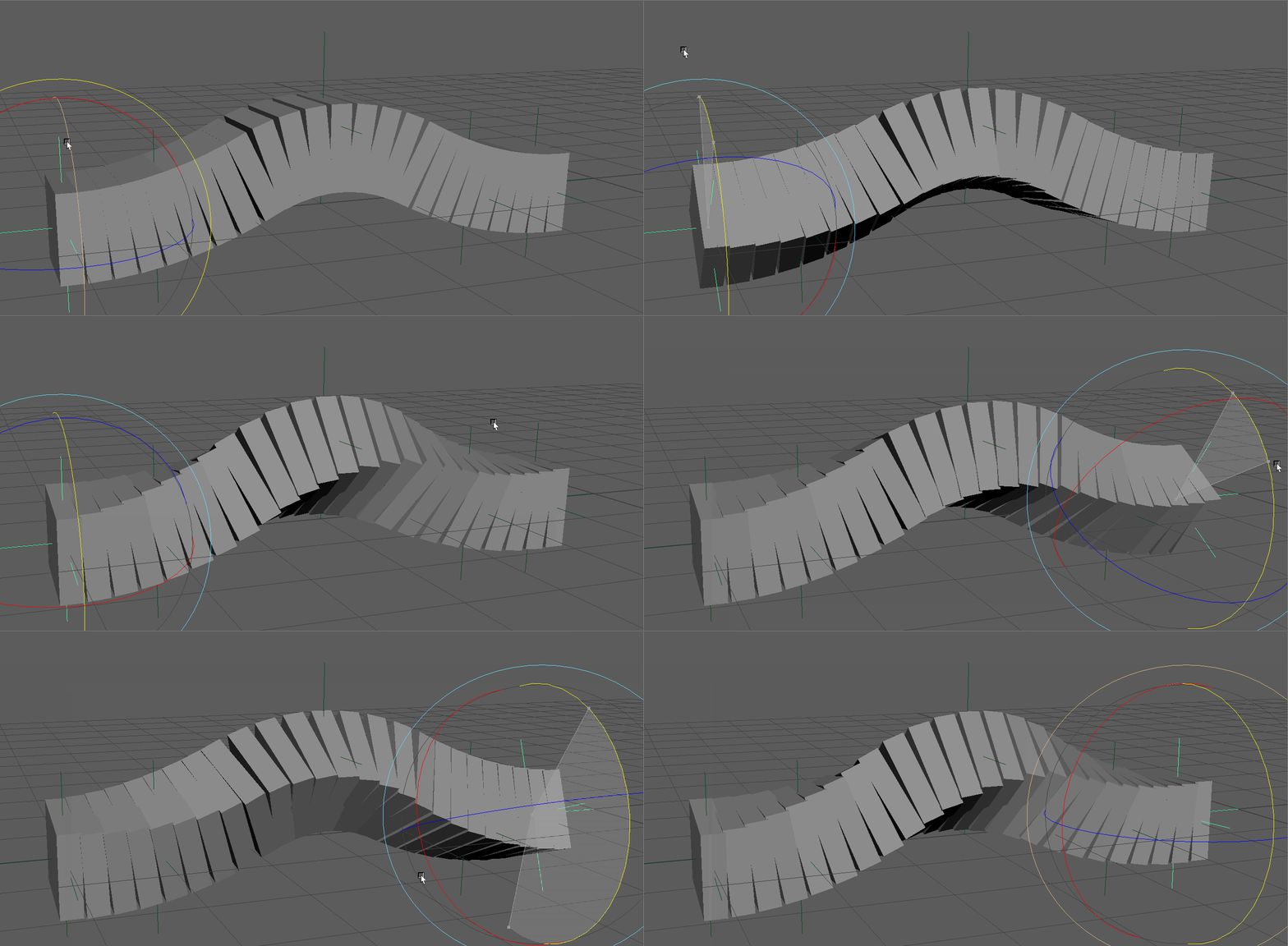
Set the
twistTypeattribute to 0 (StartEnd).
mc.setAttr('%s.twistType' % spline_node, 0)
Segment Twist
Control joint twist using start and end points.
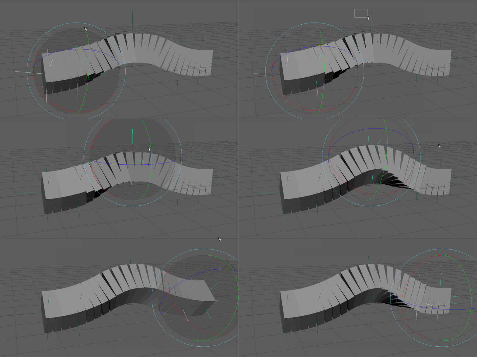
Set the
twistTypeattribute to 1 (Segment)
mc.setAttr('%s.twistType' % spline_node, 1)
Falloff (Linear/Quadratic)
The distribution of both twist and scale can be controled linearly or using a quadratic s-curve
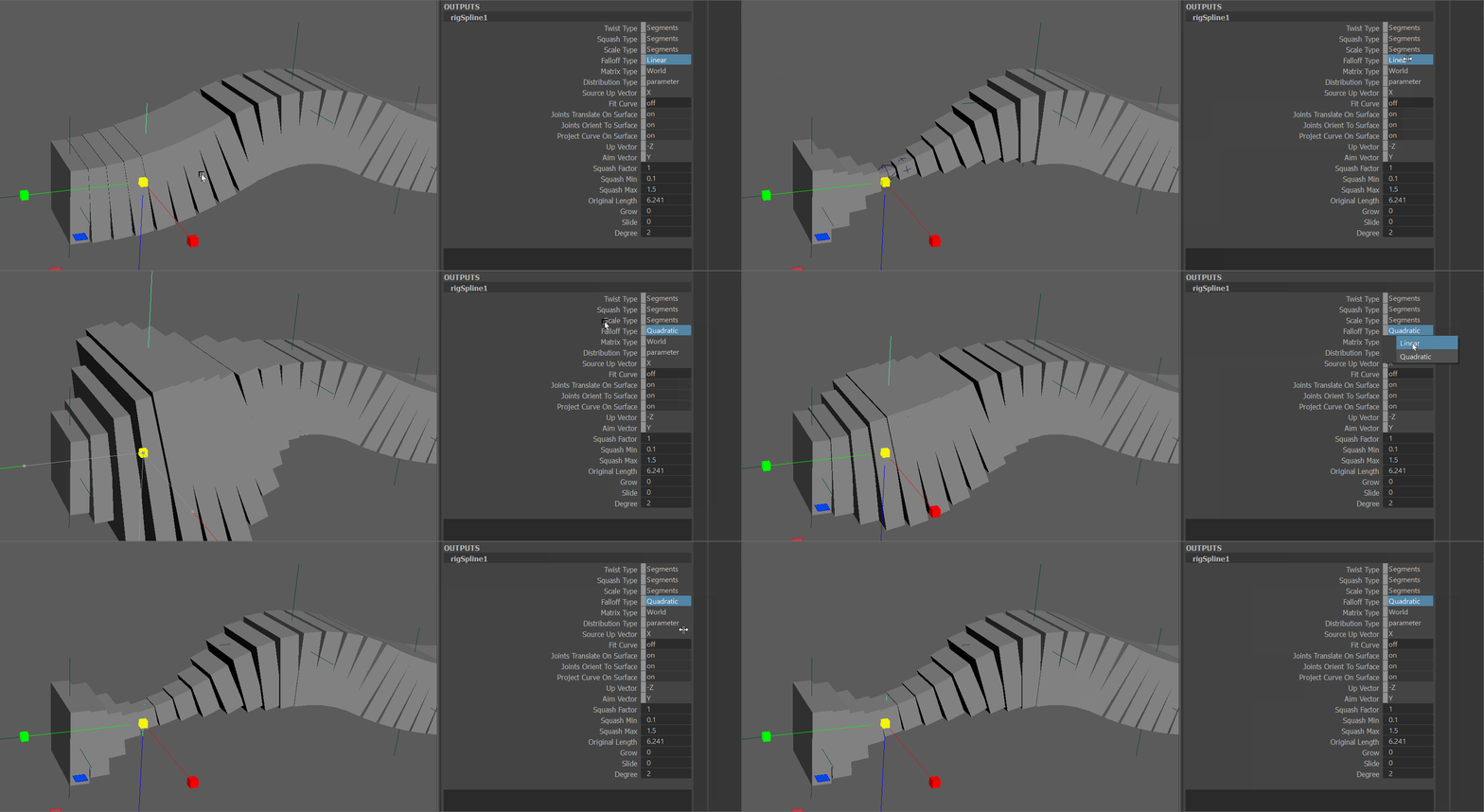
Set the
falloffTypeattribute to 0 or 1 (Linear Quadratic).
mc.setAttr('%s.twistType' % spline_node, 1)
Up/Aim Vectors
The following attributes can be used to control the aim and up vectors of the calculation.
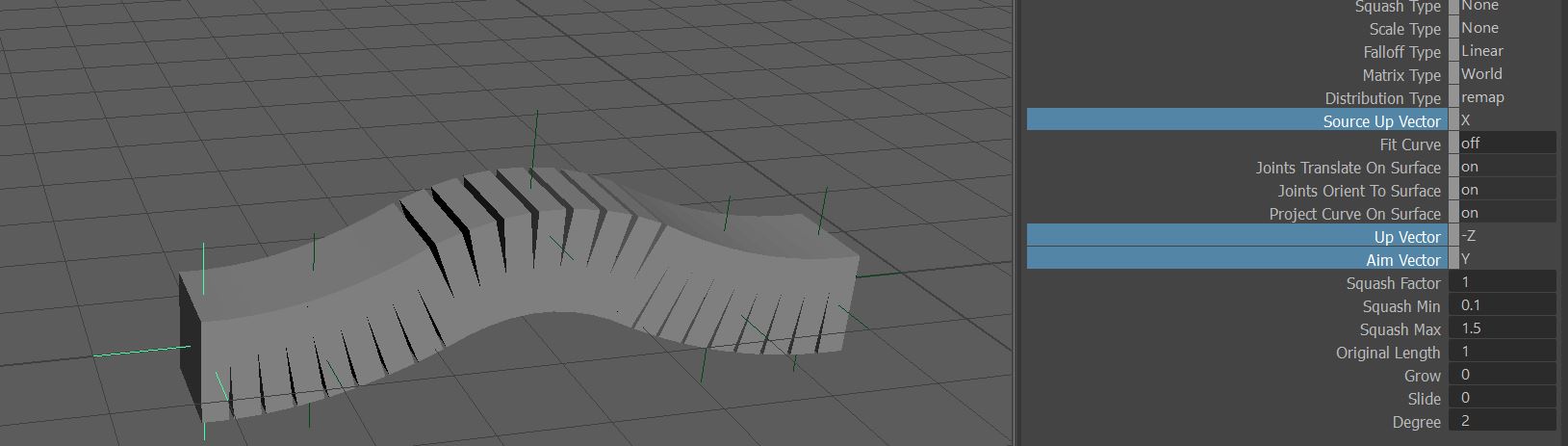
Source Up Vector
The axis of the input transform to be used as the up vector in the calculations.
Up Vector
The up axis of the output transform to be aligned with the source transforms up vector.
Aim Vector
The axis of the output transform to be aligned to the tangent of the spline.